Professional Gas Burner Head Installation Technical Guide: Ensuring Optimal Performance and Safety
This professional guide details the correct installation process, key techniques, and precautions for gas stove burner heads. Learn how to achieve perfect alignment, gas-tight connections, and performance optimization to ensure safe and reliable operation.


Introduction: Installation Quality Determines Product Performance and Lifespan
As the core component of gas stoves, the installation quality of burner heads directly affects combustion efficiency, usage safety, and product lifespan. Improper installation can lead to serious issues including uneven flames, gas leaks, and excessive CO emissions. This guide systematically introduces professional-grade gas burner installation techniques to help installers and technicians master key points.
Part 1: Pre-Installation Preparation
1.1 Workspace Assessment
- Ensure well-ventilated installation area away from flammable materials
- Check cooktop surface levelness (maximum tolerance ≤2mm/m)
- Verify gas type matches burner specifications (Natural Gas/LPG)
1.2 Tools and Materials Preparation
Essential Tools List:
- Digital level (accuracy 0.1°)
- Torque wrench (range 5-25N·m)
- Gas leak detection solution or electronic detector
- Specialized sealant (heat resistance ≥250℃)
- Pipeline cleaning brush set
1.3 Component Inspection Process
- Check burner casting integrity – no pores or cracks
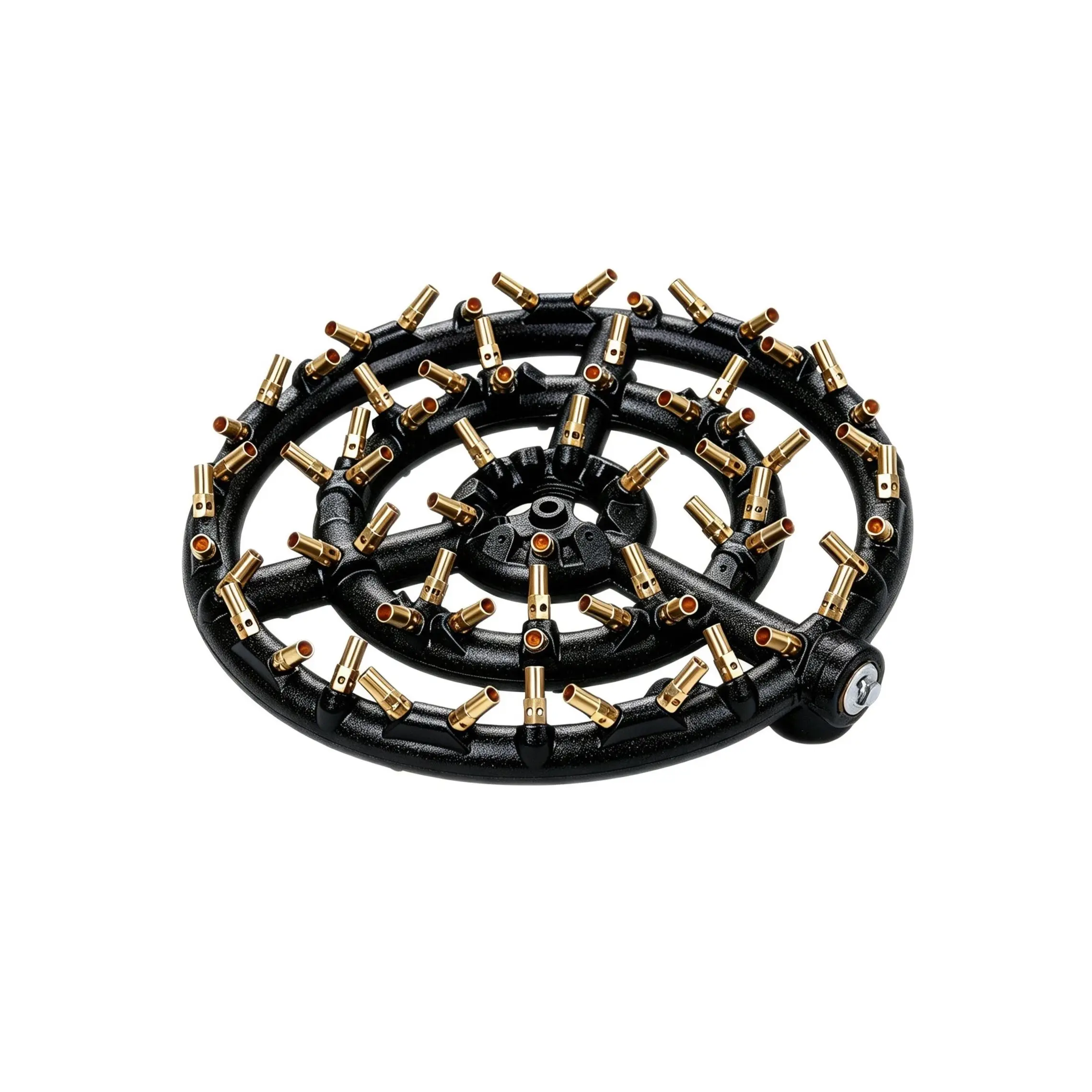
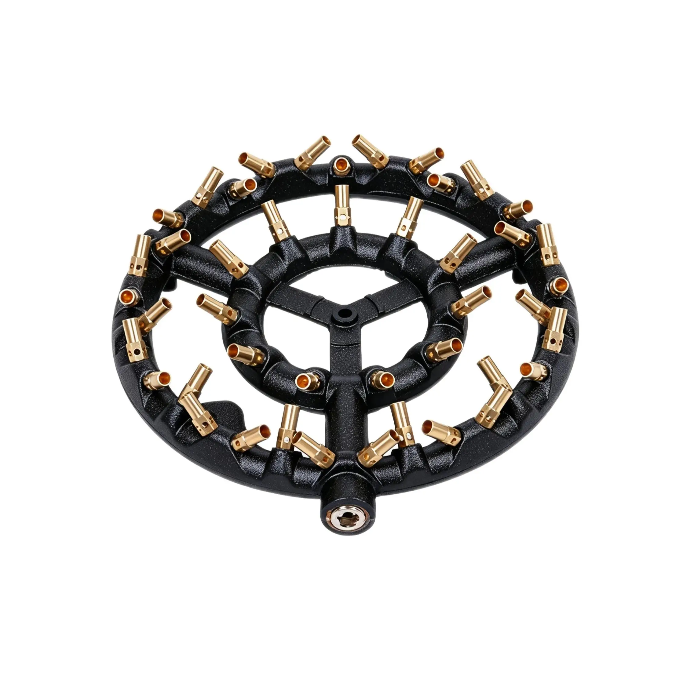
- Confirm flame distributor ports are clear and unobstructed
- Verify seal gasket elasticity and integrity
- Check ignition electrode and thermocouple alignment
Part 2: Step-by-Step Installation Technical Points
2.1 Base Installation and Leveling
Operation Steps:
- Clean installation base, ensure no oil stains or impurities
- Place burner base, check levelness using level instrument
- Use stainless steel shims for fine adjustment if needed
- Tighten fixing bolts in diagonal sequence, torque controlled at 8-10N·m
2.2 Gas Pipeline Connection
Key Considerations:
- Use specialized gas hose, length not exceeding 1.5 meters
- Use dual sealing at joints (gasket + thread sealant)
- Avoid sharp bends in pipeline routing, maintain natural curves
- Reserve thermal expansion compensation space
2.3 Ignition System Alignment Adjustment
Precision Alignment Standards:
– Ignition electrode to flame distributor distance: 3.5±0.5mm
– Thermocouple to flame distance: 2.0-3.0mm
– All electrodes to metal parts insulation resistance ≥10MΩ
Part 3: Key Quality Control Points
3.1 Leak Testing Process
- Initial Detection: Use leak detection solution at all connection points
- Pressure Test: Apply 1.5 times working pressure, maintain for 3 minutes
- Final Verification: Test at working pressure, pressure drop ≤10Pa/min
3.2 Combustion Performance Debugging
Air Mixture Ratio Adjustment:
- Observe flame color: should be uniform vivid blue
- Adjust air shutter until no yellow tips or flame lift-off
- Verify using flue gas analyzer: CO≤0.05%, O₂=3-5%
3.3 Safety Device Function Verification
- Flame failure device response time: ≤10 seconds
- Ignition success rate: ≥98% (20 consecutive tests)
- Accidental flame-out re-ignition time: ≤3 seconds
Part 4: Special Installation Scenario Handling
4.1 Built-in Cooktop Installation
- Ensure precise cabinet cutout dimensions with edge sealing
- Reserve adequate ventilation space (bottom ≥100mm²)
- Prevent heat conduction to countertop using insulation materials
4.2 Commercial High-Power Burner Installation
- Reinforce support structure to prevent thermal deformation
- Independent gas supply line with pipe diameter matching power requirements
- Use high-temperature resistant materials (≥600℃) in high thermal load areas
4.3 Multi-Burner Array Installation
- Establish unified baseline to ensure all burner alignment consistency
- Group control to avoid excessive simultaneous starting current
- Rational layout to ensure burners don’t interfere with each other
Part 5: Post-Installation Testing and Acceptance
5.1 Performance Testing Checklist
- Smooth transition between all power levels
- Flame uniformity (no visible differences)
- Ignition response time ≤2 seconds
- Operating noise ≤55dB
- Surface temperature complies with safety standards
5.2 Documentation Requirements
- Installation date and personnel information recording
- Key parameter measurement data archiving
- Customer confirmation signature
- Maintenance file establishment
Part 6: Common Problem Solutions
6.1 Uneven Flame Treatment
- Check flame distributor cleanliness
- Verify gas pressure stability
- Adjust air mixture ratio
6.2 Ignition Failure Troubleshooting
- Check electrode spacing
- Test igniter output voltage (should be ≥8kV)
- Clean ignition electrode carbon deposits
6.3 Abnormal Noise Handling
- Check component resonance
- Verify airflow stability
- Eliminate foreign object interference
Conclusion: Professional Installation Creates Excellent Value
Proper installation is not only a prerequisite for normal product operation but also crucial for achieving optimal performance and extending service life. By following the standardized processes in this guide, installation quality can be significantly improved, reducing after-sales issues and creating better user experiences for customers.